I've recently been on holiday in NSW, and my uncle gave me a pile of sapphire bearing gravel which he'd added gold to. I had lot of fun sifting through it and I'd love to go back and collect more of the stuff.
I got the impression that the minerals in the gravel would glow under UV light, so I bought a UV flood light and some electronics to make a UV strobe. I could use the strobe to tell me if I'm digging in the right place. Only 1% of the bits of gravel glowed under the spotlight so that was a bust.
I'm also thinking of looking for gold. I've been thinking a lot about how I could make my own metal detector.
I purchased a solder-your-own metal detector kit, MDS-60, and it's not great. I could detect a 5c coin from around 5mm. It's a start, but I'd like to build a metal detector that can compete on sensitivity to small pieces of gold as an expensive unit.
Here is a video of the device in action
With a bit of fine tuning I was able to achieve detection at about 1cm.
All for now, Boston
Update 4/3/2025:
MDS-60 Metal Detector Kit
The MDS-60 is a very simple solder-your-own metal detector kit. It only has 3 active components: two PNP transistors and one NPN transistor (don't get these mixed up!). I'm impressed with how well this works for such a simple design.
The device shows a positive response to a 5c coin at around 2cm, and a strong negative response to ferrite.
Here is the best circuit diagram I've seen online:
I believe the circuit detects metal based on changes in the Q-factor of the resonator formed by the inductor coil (L1) and various capacitors. Positioning a conductor near the coil will lower the Q-factor and positioning a ferrite near the coil will raise the Q-factor. A resonator with a low Q-factor dissipates energy more quickly than one with a high Q-factor. Thus, more current is needed to drive the circuit. This current is detected, amplified and sent to the output.
L1 is a coil of wire etched directly into the two-sided PCB. As well as the main winding, it has an extra loop that connects to C2 in the diagram above. I have seen suggested that the coupling between the extra loop and and the main winding is used to detect pieces of metal nearby, but I like the the Q-factor explanation better. The extra loop provides feedback which is amplified and sent back into the main winding.
All for now, Boston.
Radio-Kit M185.2v1
I have assembled a metal detecting probe using the Radio-Kit M185.2v1
When assembled with a 20cm coil, the device was sensitive to a 5c coin at 10-15 cm, and not sensitive to 3mm gold. When assembled with the probe, the device was sensitive to a 5c coin at about 2cm, and sensitive to 3mm gold at about 1/2 cm. I hope to go down to the creek and poke around under rocks with it. Maybe I can optimise the probe by increasing or decreasing the number of coils or removing the ferrite
Pulse Induction metal detectors usually create a magnetic pulse and then sample the signal a moment later as it takes time for the pulse to decay (having metal near the coil slows down this decay time due to energy being stored in eddy currents within the metal). What is interesting is that this circuit uses only one 555 chip for timing and only 2 op amps. The design is based on the widely available Pirate Metal Detector design. (I guess) the circuit works by filtering the signal across the coil, integrating over the time it takes for the signal to decay.
All for now,
Boston
Update 28/4/2025
I made a new probe with insulated wire for the coil and coaxial cable to connect to the pcb. The old probe used magnet wire and audio cable. I did this to reduce the capacitance of the probe. I have read that having less capacitance helps with a PI design.
I tested both probes. The old probe picked up a 5c coin from 1cm away, and did not pick up a 3mm piece of gold. The new probe picked up a 5c coin at maybe 1.5 cm, and did not pick up a 3mm piece of gold.
I think if you improve the capacitance, you also need to vary the damping resistor, or you can experiment with changing the inductance. I will experiment with varying the number of windings in the coil, some other time.
Boss
Update 18/5/2025 - Induction Balance
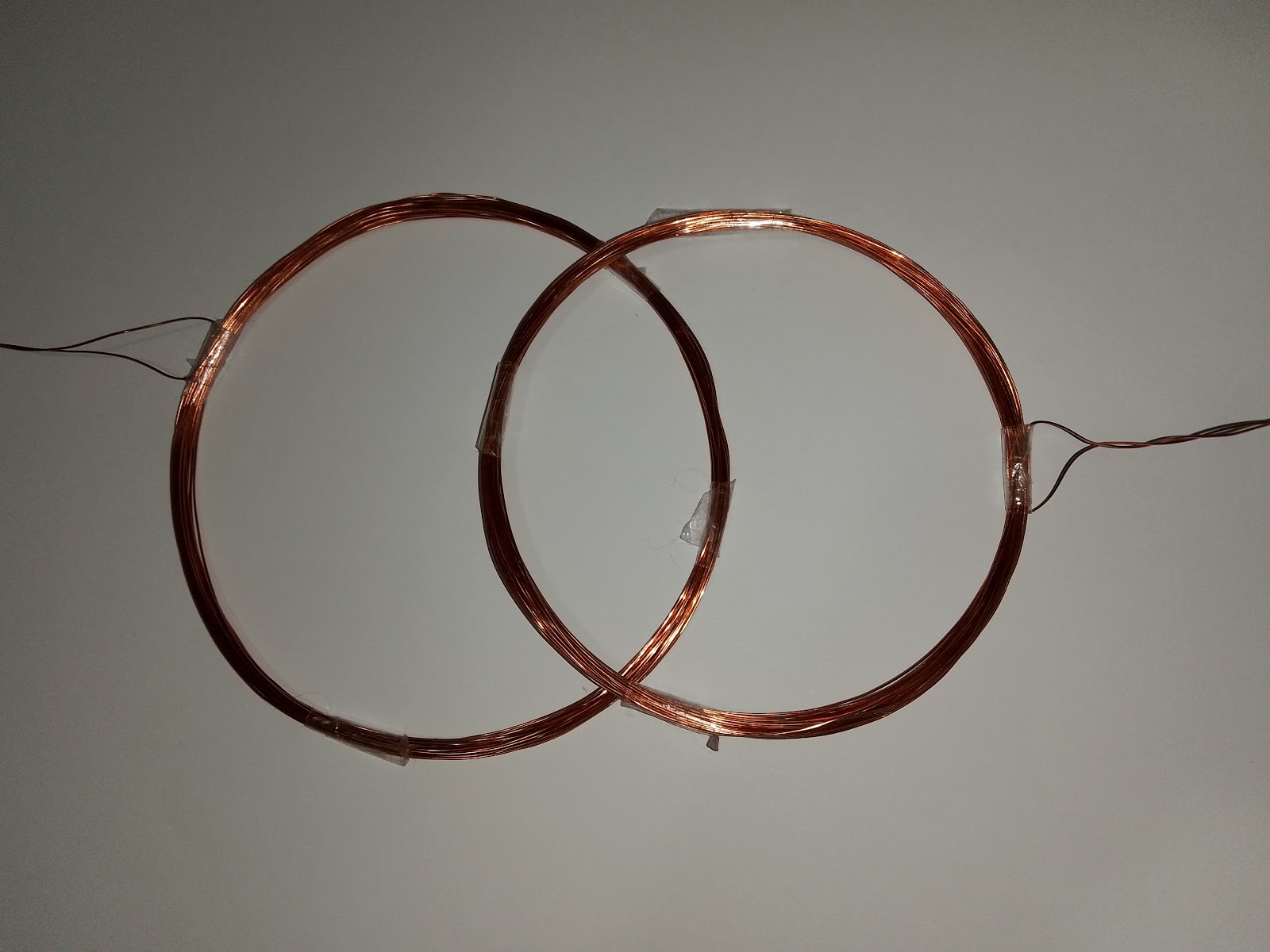
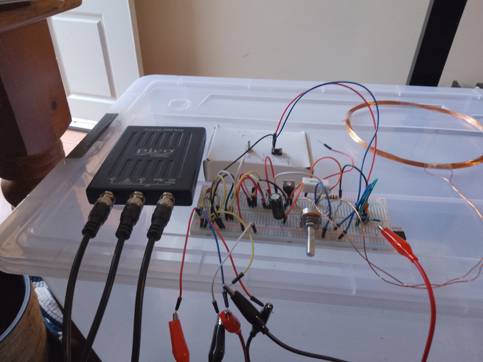
I've successfully demonstrated the principle of an induction balance metal detector. I connected one coil of wire to a signal generator and another to an oscilloscope.
Here we see the coils fully overlapping, and the signal on the oscilloscope:

Clearly there is a lot of high-frequency noise on the receiver (red). There is some noise in the signal taken directly from the signal generator output (blue)
Compare this to when the coils are partly overlapping and partly not overlapping:
We see that the EMF from the region where the receiver coil is overlapping transmitter coil cancels with the EMF from the region where they are not overlapping.
I built this circuit taken from Inside The Metal Detector by Carl Moreland:
Here the coils are fully overlapping:
Here we have induction balance:
This is the result from placing a pair of pliers within the electromagnetic field of the induction balance:
It feels good to get stuff done. I'll be going to Lightning Ridge in two weeks to poke around for opals.
All for now, Boston.
PS Today I tried to detect smaller objects but the circuit behaved like it had a few loose wires.
Update 21/5/2024
I've rebuilt the circuit on a different breadboard. The signal on the receiver was fuzzy from high frequency noise. I replaced R7 with a 15 ohm resistor and started getting a better signal:
I used a figure-eight coil to reduce EMI, zoomed in on the oscilloscope, and created an induction balance:
Using a big roll of tie-wire made an obvious signal. Putting a $2 coin near the coil gave this result:
There is some signal there, if you use your imagination, but it was hard to maintain the induction balance anyway. I can identify 3 sources of improvement for this circuit: use a PCB rather than a bread board to minimise the area susceptible to EMI, use a more expensive op-amp (than NE5534P Low Noise High Speed Op-Amp Linear IC), or use a more professionally made coil arrangement.
That's as much experimenting with this circuit I will do now,
Boston
PS don't leave batteries in a battery holder with loose wires, when not in use. It will short circuit and melt:
Update 21/5/2024 Pulse Induction:
A bit of an escalation from the previous circuit, I plan to make the analog front end of a pulsed induction type metal detector:
The signal coming in on the left hand side of the image should look like this:
A period of 1.5ms gives a frequency of about 666Hz and an on time of 100µs gives a duty cycle of about 6.5%
Here is the breadboard:
Here are the input and output signals:
As you can see, the input pulse has not enough voltage to trigger the circuit. It should be 5v. I'll amplify the input with an op-amp, tomorrow.
Boston.
Update 22/5/2025
I was able to amplify the input signal to a desirable level. I had to replace C2 with a 100nf capacitor. I got the pinout wrong for some of the transistors and I decided to pull the circuit apart, put everything away, and try again later.
Boston
I've just learned that you can't use a battery as a power supply without some form of voltage regulation because batteries have high impedance; they don't provide the power when it's needed like for driving op-amps.
Update 10/6/2025
Today I went out and bought the Minelab Gold Monster 1000. I was a bit disappointed with its range when detecting a 5c coin and also when detecting a 3mm gold nugget.
A bigger coil might mean deeper penetration, but I don't think it would improve sensitivity to small gold.
While I was waiting for the battery to charge I tested out a probe I built for the Clone Pi W, which I bought off eBay. I think I should much around and plot number of windings of the probe coil vs inductance and detection range.
All for now,
Boston
PS I just tested the Gold Monster in my backyard in all metal mode and it turns out my backyard is strewn with bits of iron. I picked up a small screw about 6mm long, so my initial review might have been a bit pessimistic. It works. It's good to be able to find small objects that might have been passed up by previous metal detectors. I plan to take it out tomorrow and see what I find.
Update 15/6/2024:
Today I built my first circuit board. Well, not the first, but the others were a long time ago. I made a +-5v regulated power supply:

I'll chalk this up as a "learning experience" when it comes to soldering on a proto-board. I have this yellow insulated solid core wire. I can strip the end of the wire to make a trace between the components on the proto-board, and the insulated part of the wire makes a nice handle to hold the wire in place. Once the bare wire is soldered in place, I can snip off the insulated part.
All for now,
Boss
Update 24/6/2025
I made a huge mess trying to pot the above circuit using araldite two-part epoxy that leaked everywhere and didn't set, and I found it awkward working with leads soldered directly to the circuit board.
I de-soldered everything and cleaned it with isopropyl alcohol and used two halves of a 6 pin IC socket where I had previously soldered the leads to the board. I think I did a nicer job at soldering:
I am a bit worried about the flimsy attachment of the voltage regulator ICs since they're not being potted:
I'm just going to leave them how they are, but if it turns out to be a problem, I will replace the heatsinks with ones long enough to be glued directly to the circuit board.
Finally, the IC sockets were just the right size to accept bread-board wires and I used these to hook up two 9v batteries and test the circuit. The circuit worked fine and had a rail-to-rail voltage of 9.86 v
All for now,
Boston Brooks
Update 24/6/2025-2
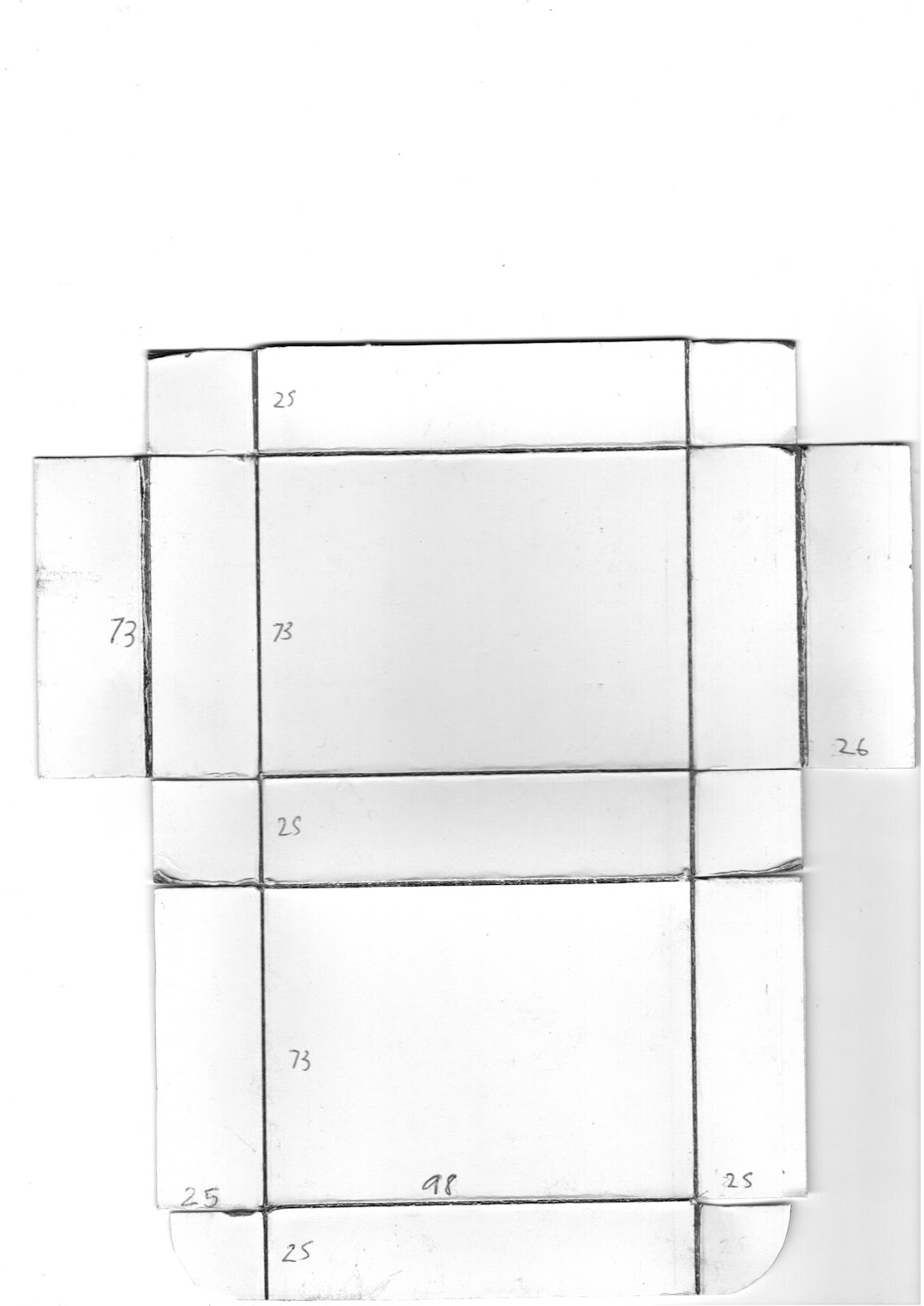
I made a nice little box to contain the circuit board and batteries:
I started with some 1mm card, which I drew the outline of the box on. Then I cut out the shape of the box. Near the ends I used a scalpel because I was having trouble finishing with scissors. Then I gouged out fold lines with a ball point pen and folded along the lines. I needed to trim the cardboard here and there to make everything fit together, and the whole thing could do with a 1mm adjustment here and there.
The power supply is now fully assembled. I give myself a B grade. I bought enough parts to assemble another power supply and make it nicer looking, but that wont be a high priority.
All for now,
Boss
Update 17/7/2024 Pulse Induction:
I rebuilt the pulse induction circuit from earlier, using the 5 volt regulated power supply:
I had to set VB- from -9v to -5v because the IRF740 MOSFET was getting hot and the circuit was making a sizzling sound. Here is the signal coming in from the left (red) and the signal going out on the right (blue)
I placed a pair of pliers inside the coil. I was expecting the decay signal around the 250us mark to decay more slowly. Unfortunately there was no change. I will have time to much around with the circuit board, tomorrow.
All for now,
Boston
Update 18/7/2025
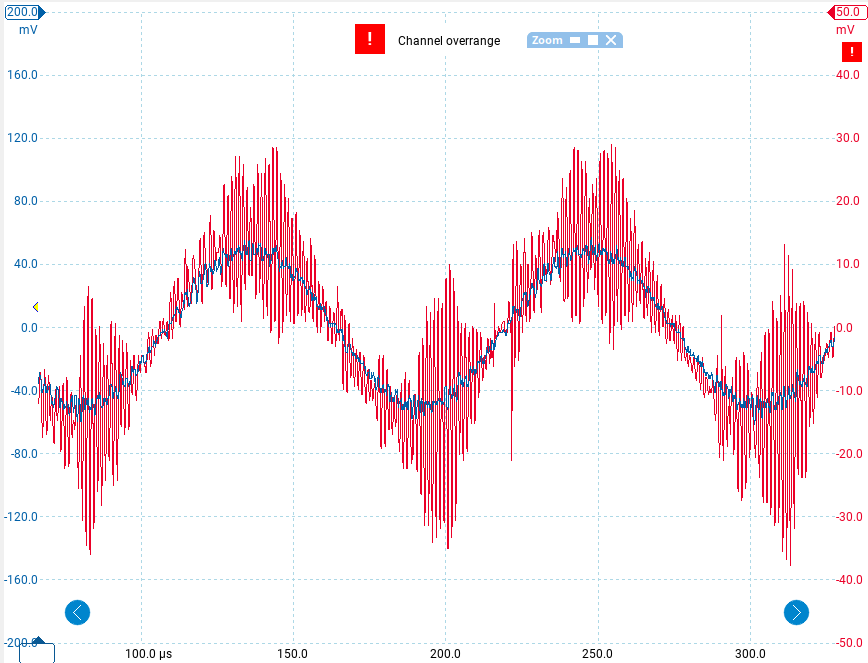
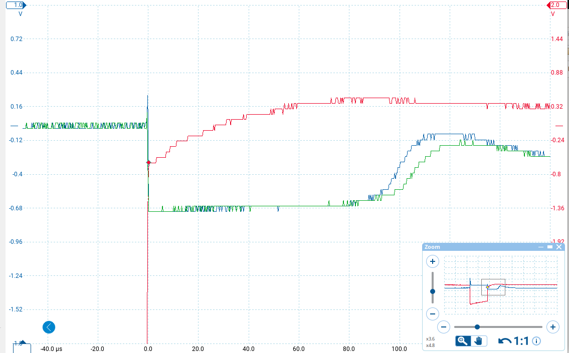
I've managed to get the above circuit to work by unplugging and replugging some components. I only powered the circuit for short bursts because the MOSFET was getting hot. I put a 1000:1 voltage divider across the metal detector coil and saw a 1v pulse on the oscilloscope (I forgot to take a screenshot). I was able to get a decent output signal that demonstrates the action of a Pulse Induction metal detector:
The red line in the image above is the voltage at the gate of the MOSFET, the blue and green signals are across the the coil, but have been clamped within +-0.7v by a pair of diodes, as in the schematic. As you can see, It took the green signal longer to settle towards zero than the blue signal. This is because for the green signal I placed a pair of pliers inside the coil, and the extra energy stored in the coil due to the interference of the pair of pliers with the coil's magnetic field took a little longer to dissipate.
All for now,
Boston.
Update 17/10/2025:
I've put together the simplified magnetic field probe circuit from Inside The Metal Detector 3, on a breadboard:
I used it to take a look at the output from my Gold Monster 1000 metal detector:
For smaller signals, when the probe was further from the metal detector's coil, the waveform looked more triangular. For larger signals, the waveform looked more like a square wave, so there is a problem with linearity. I believe the real signal is a sine wave. I didn't have a 47pf capacitor so I used a 33pf and a 10pf in parallel, and I am using whatever high bandwidth op-amp they were selling in Jaycar, so that might explain it. The frequency is about 45khz.
I lent the book to a family member in the hope of inspiring a common interest, so I can't read up on how to test the circuit practically. I do have a few "not triple-A rated" metal detector circuits I can test it on. The hard part is choosing the right components on au.mouser.com and getting the circuit properly tuned.
All for now,
Boston


Comments
Post a Comment